
Cross roller type toothless slewing ring
Home>Product Center > HJ series single row cross roller type
Home>Product Center > HJ series single row cross roller type
Single-row interspersed roller slewing ring (HJ series)-gearless structural features, performance, and scope The assembly gap is small, and the accuracy requirements of the device are high. The rollers are arranged in a 1:1 interspersed arrangement, which can receive axial force, tilting moment and large radial force together, and are widely used in lifting and transportation, construction machinery and military industry. Product. Slewing bearings are widely used in the actual industry. They are called "joints of machines". They require relative rotational movement between two objects, and they need to receive axial force and diameter together....
Single-row interspersed roller slewing ring (HJ series)-gearless

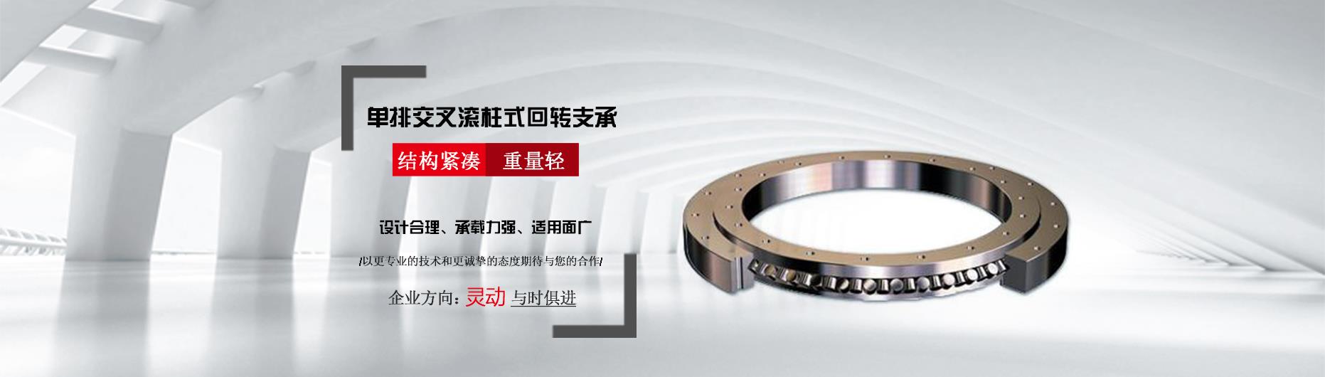
Structural features, performance, scope of application
The larger the radius ratio of the single-row interspersed roller slewing ring is, the lower the additional static capacity and the shorter the service life. Even if the heat treatment hardness of the raceway and the depth of the hardened layer meet the specification requirements, the radius ratio cannot be effectively controlled. Capacity and service life are still not up to the standard value, which is often overlooked, but it is an important parameter that affects the performance of the slewing ring. Slewing bearings are widely used in the actual industry. They are called "joints of machines". They are mechanical places that require relative rotational motion between two objects and also receive axial force, radial force, and tilting moment. An important transmission component necessary.
Improper adjustment of the gap between the large and small gears during installation. If the requirements are not met, the two teeth meshing poorly during work, resulting in broken teeth, the gap should be adjusted as required; the meshing gap adjustment with the small gear is not performed at the tooth jump position as required, and the pinion gear meshes with the large gear tooth jump position during work When the gear is stuck, it will form a broken tooth. There should be a green paint position on the way to mesh with the pinion gear. After the installation, the large and small gears are poorly meshed and form broken teeth. The two gears shall be meshed in parallel; the bolts of the slewing support device are not tightly fixed, and the large and small gears are not properly meshed, resulting in broken teeth. The bolts shall be tightened as required.


